(Click for an enlarged version of this diagram)
The Phil-Mont Repeater System currently
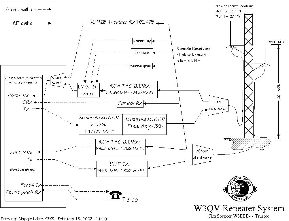
consists of a VHF repeater with an input on 147.63 MHz (91.5 PL required),
an output on 147.03 MHz and a UHF repeater with an input on 449.800 (186.2
PL required) and an output of 444.800.
Both repeaters run approximately 40 watts to the antenna. The two repeaters are usually tied together so that audio received on either band is re-transmitted on both bands. Appropriate control codes allow separation of the two repeaters for a timed period of operation.
Antennas are Station-Master type with gain figures in the area of 5 dB located on th e tower at about 150 feet for an effective height of about 600 feet above mean sea level (MSL). 7/8" hardline is used for feedlines to both antennas. A separate Discone antenna is available at ground level in the event of a complete failure of other equipment.
The repeater building is electrically heated and air-conditioned. A 8KW propane-fueled generator is automatically started and transferred in the event of commercial power failure.
VHF System: An RCA TAC 200 receiver (91.5 Hz PL) is fed to the Link Communications RLC2A controller main channel. Audio from the controller is fed to a Motorola MICOR continuous-duty exciter and final amplifier. A PL of 91.5Hz is transmitted on the output.
UHF System: An RCA TAC 200 receiver (186.2 Hz PL) is fed to the Link controller at Link 1 input. Audio from the controller is fed to theUHF transmitter, and a PL of 186.2 is transmitted on the output.
Link RLC2A Controller: This controller board and chassis is capable of 5 inputs.
Port 1 (designated as R1-VHF), Port 2 (designated as R2-UHF), Port 3 (unassigned), Port 5 (Control receiver designated as CRX). All off-site receivers AND the main Roxborough receiver are selected by the signal-to-noise ratio (S/N) to the LVS-8 Voter and the result fed to Port 1 input. The UHF input is fed to Port 2 and appears as a combined audio input to the controller.
Outputs are available from Port 1 and Port 2 under normal conditions. Port 4 output is used only in phone patch operation. Port 5 can be retransmitted only for monitoring purposes.
Control codes may be entered into the controller on a priority basis from the telephone line, the control receiver (70 cm band) , and either of the two RCA receivers. A masking tone covers any incoming tones to prevent interception. Any of the five Control Operators can enter changes for you when necessary.
We have designated Macros as follows:
|
M1: Normal operation |
PL required |
VHF chime |
|
M2: After midnight |
PL requred |
Staircase up |
|
M3: Net operations |
PL not req |
Single high tone |
|
M4: Weather macro |
PL not req |
Fast staircase up |
|
M5: Interference macro |
PL required |
No tone, no tail |
Any input from UHF carries a staircase-down courtesy tone. Both M4 and M5 have reduced time-out cycles of 75 seconds. Normal time-out is three minutes. Verbal responses appear on the output for any control codes entered.
Redundancy was a prime consideration of the Repeater Committee. We have plug-any-play spares for the VHF exciter and final and, when the UHF transmitting equipment is received, for UHF exciter and final. A back-up controller (RC-85) chassis is available should the RLC2A fail or need to be removed for servicing.
-Jim W3BBB (HTML version and diagrams by Maggie K3XS)
